Product recommendation
I. Main Nozzle: Precise Positioning and Pressure Matching to Reduce Ineffective Air Consumption.
The main nozzle is the power source for the initial acceleration of the weft yarn. Its position and pressure directly determine the airflow utilization rate. Energy waste caused by "over-pressurization" and "positional misalignment" must be avoided.
1. Installation Position: Precise calibration based on the airflow cone shape.
Core Principle: The distance between the main nozzle and the first irregularly shaped reed tooth determines the degree of airflow diffusion—if the distance is too close, the airflow will not be fully focused before entering the reed groove, easily colliding with the reed teeth and dissipating energy; if the distance is too far, airflow diffusion will intensify, failing to effectively pull the weft yarn.
Practical Method: Use a stroboscope to observe the shape of the airflow cone (the airflow cone is conical, with the tip pointing towards the center of the reed groove). Adjust the distance so that the airflow cone just covers the reed groove inlet, and the cone angle is minimized (ideal cone angle ≤ 30°). For example, a recommended distance for a certain model is 15-20mm, which needs to be fine-tuned based on the reed groove width (usually 4-6mm).
2. Pressure Setting: The "Minimum Effective Pressure" Principle
Matching Pressure with Weft Yarn Characteristics: The pressure must take into account the weft yarn count (lower pressure for fine denier yarns, moderately higher pressure for coarser yarns), fabric width (slightly higher pressure for wider fabrics), and machine speed (high speed requires short bursts of high pressure, low speed allows for lower pressure).
Adjustment Standard: Use "few weft breaks, no loose edges/weft shrinkage" as the baseline, gradually reducing the pressure to the critical value. For example, with 60S pure polyester yarn, at a speed of 650 rpm, the main nozzle pressure can be reduced from 0.4 MPa to 0.32 MPa (a 20% reduction), without a significant increase in weft yarn breakage rate, resulting in a significant reduction in air consumption.
Risk Warning: Excessive pressure can cause rapid weft yarn untwisting and breakage (especially with weakly twisted yarns). Simultaneously, the airflow impacting the warp yarn increases frictional resistance, indirectly increasing air consumption.
II. Auxiliary Nozzles: Refined Control of Process Parameters (Accounting for 75% of Air Consumption, the Core Optimization Target). Auxiliary nozzles are responsible for the tension and acceleration of the weft yarn throughout its flight. The coordinated optimization of their pressure, time, position, and type is key to reducing air consumption.
1. Pressure Setting Strategy
During weft flight, the airflow velocity from the auxiliary nozzles must be greater than the initial velocity of the weft yarn (i.e., the weft yarn's flight speed). The weft yarn's leading edge must always be under the influence of high-speed airflow. This requires the auxiliary nozzle's air pressure to be greater than the main air pressure. Furthermore, as the weft yarn's leading edge flies forward, the auxiliary nozzles must sequentially open and close their air supply valves to prevent the weft yarn from being pushed forward and squeezed backward.
However, in actual production, the auxiliary nozzle pressure is usually determined by increasing the predetermined main nozzle pressure by 0.02~0.1 MPa. Care should be taken to reduce weft yarn breakage and save air consumption.
2. Spraying Time: "Advanced Opening + Precise Closing"
Opening Time (Lead Angle): Each auxiliary nozzle group should open 10°-20° before the weft yarn arrives (set via the loom encoder) to ensure that the airflow acts on the weft yarn's leading edge in advance.
Closing Time (Lag Angle): The last auxiliary nozzle group closes 20° after the weft yarn reaches the selvage (20° lag angle) to avoid closing too late and causing airflow to impact the warp yarn. Note: The closing time must not exceed "20° after the weft yarn reaches the selvage," otherwise the nozzle will have already entered below the lower warp yarn, and the airflow will be completely ineffective.
Total Auxiliary Nozzle Spraying Time: Controlled between 40°-80° (corresponding to a loom speed of 600-800 rpm). Too long a time will increase air consumption, while too short a time can easily lead to weft yarn slack.
The starting time settings for each auxiliary nozzle group follow the following pattern:
The spraying time of the first four auxiliary nozzle groups is shorter than that of the last four auxiliary nozzle groups. This is because when the first four auxiliary nozzle groups are working, the main nozzle is continuously working, sharing some of the weft insertion task with the auxiliary nozzles.
The last four auxiliary nozzle groups do not have the assistance of the main nozzle, so their working time needs to be extended to meet the weft insertion requirements. In actual work, sometimes it is necessary to deliberately extend the working time of the last auxiliary nozzle group to reduce defects such as weft yarn rebound.
3. Installation Location: "Angle Consistency + Group Matching"
Angle Parameter Standardization:The auxiliary nozzle must be aligned with the center of the reed groove. Set the spray angle α = 8° (upward) and spray direction angle β = 5° (backward) to ensure the airflow enters the center of the reed groove and converges with the main airflow.
Group Matching: Auxiliary nozzles of the same model have tolerances in their α and β angles (e.g., imported nozzles have an α deviation of ±0.5°, domestic nozzles ±0.7°). They must be grouped according to the measured angles (e.g., Group A α = 7.5°-8.5°, Group B α = 8.5°-9.5°). Nozzles within the same group should be used in combination to avoid airflow direction disturbance.
Auxiliary Spray In-Machine Adjuster Auxiliary Calibration:Use a dedicated adjuster. Place the sensor in the reed groove to receive the airflow signal and display the real-time deviation between the airflow center and the reed groove center. Manually fine-tune the nozzle angle until the deviation is ≤0.5mm.
Auxiliary Spray In-Machine Adjuster Calibration:Use a dedicated adjuster. Place the sensor in the reed groove to receive the airflow signal and display the deviation between the airflow center and the reed groove center in real time. Manually fine-tune the nozzle angle until the deviation is ≤0.5mm.
4. Nozzle Type: "Multi-hole clustering + low-resistance design" is preferred.
Structural Comparison: Single-hole nozzles have fast airflow diffusion and short range; generally, multi-hole nozzles (such as 19×φ0.05mm regular hexagonal arrangement) are considered to have better airflow clustering and longer range (30% more range than single-hole nozzles).
Selection Recommendation: Prioritize multi-hole nozzles (especially for wide-width looms), paired with streamlined nozzle housings (to reduce airflow friction resistance), which can reduce single-nozzle air consumption by 15%-20%.
III. Solenoid Valve: Shorten effective jet time and reduce "ineffective delay". The opening and closing delay of the solenoid valve (0.06s opening delay, 0.04s closing delay) leads to wasted airflow, and "ineffective jet time" needs to be compressed through parameter optimization.
1. Matching of Action Time and Voltage
Effective Jet Range: The effective jet time (segment bc) is the period between the pressure rising to 90% (t1) after the solenoid valve opens and the pressure dropping to 50% (t2) when it closes, not the full opening and closing time (segment ab+cd).
Debugging Method: Monitor the solenoid valve current waveform using an oscilloscope and adjust the voltage (e.g., increase from 24V to 28V) to shorten the opening delay. Alternatively, set a "pre-opening" setting in the PLC program (triggering 5°-10° electrical angle in advance) to ensure the airflow reaches stable pressure before the weft yarn arrives.
2. Group Control Strategy and Pipeline Optimization
Independent control of the main nozzle solenoid valve and auxiliary nozzle solenoid valve: The main nozzle only opens at the initial stage of weft insertion, while the auxiliary nozzles open in groups, avoiding pressure superposition and waste caused by multiple nozzles simultaneously spraying air.
During weft insertion, the mass of the weft yarn increases with the length of weft insertion as it flies through different sections, requiring a corresponding increase in the required weft-carrying airflow velocity.
Auxiliary nozzles should ideally be supplied with air from two separate air cylinders. Since the main nozzle closes when the weft yarn is almost out of the shed, the air pressure of the auxiliary nozzles on the right side needs to be increased to prevent a decrease in weft yarn flight speed.
This separate air supply allows for independent control of the airflow pressure in the two weft insertion sections. This significantly reduces air consumption and also helps stabilize weft yarn flight.
Main pipeline diameter ≥25mm (originally 16mm) to reduce pressure loss along the pipeline (pressure drop ≤0.02MPa per 10m of pipeline);
IV. Loom speed and process coordination: Avoid "blindly increasing speed"
Relationship between speed and air consumption: For every 100rpm increase in machine speed, the number of weft insertions per unit time increases, and air consumption increases linearly (e.g., air consumption increases by 18% at 700rpm compared to 600rpm).
Determining the speed of a loom requires consideration of numerous factors. In actual production, a higher loom speed is not always better; it should be determined based on the specific circumstances of each factory to optimize efficiency and energy consumption.
VI. Summary: The Key to Systematic Energy Reduction
Reducing air consumption in air-jet looms requires adhering to the principles of "precise control + dynamic matching + system coordination":
Main nozzle: Reduce initial air consumption by using "minimum effective pressure + optimal position";
Auxiliary nozzle: Improve airflow utilization through "gradient pressure, precise timing, and group matching" (air consumption accounts for 75%, with maximum optimization potential);
Solenoid valves and air supply system: Shorten ineffective delays and segment air supply to reduce redundant airflow;
Global coordination: Dynamically adjust parameters based on loom speed and weft yarn characteristics to avoid a "one-size-fits-all" approach.
Ultimate goal: Achieve a 15%-25% reduction in air consumption per loom while ensuring fabric quality (weft breakage rate <1%, weft shrinkage rate <0.5%), while further exploring energy-saving potential through technologies such as variable frequency air compressors and waste heat recovery.

Please visit product page for more information
-
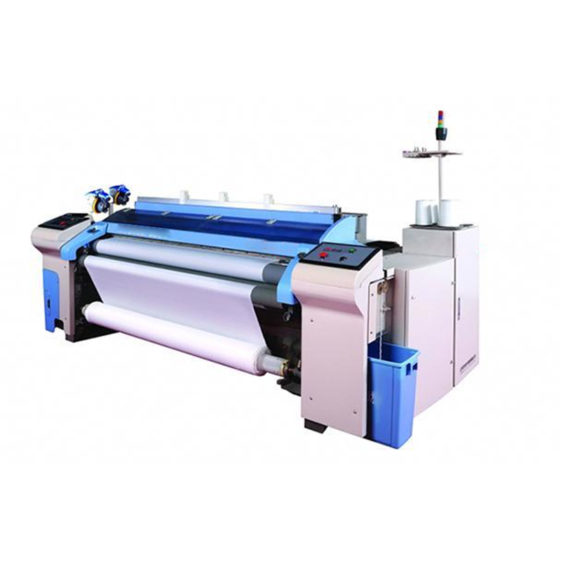
![Shuttleless With High-pressure Current Water Jet Loom Weaving Machine]()
Shuttleless With High-pressure Current Water Jet Loom Weaving Machine
The JW8200 high-speed water jet loom features a higher production efficiency than the JW400 and JW822 water jet looms, with a shift weft density and weaving speed.
More
-
- Textile factory's automatic threading machines and other textile machinery accessories have been widely used in many markets at home and abroad.
- Textile factory's automatic threading machines and other textile machinery accessories have been widely used in many markets at home and abroad.
- 280 Type C Simplex Column Steel Healds wires For Automatic Drawing-In Machine
- Heddle And Open Drop Wires 165*11*0.3 For Weaving Machine Spare Parts